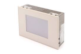


Siemens 6AV6520-0CA05-2AA0 SIMATIC OP 55
€ 547,00
The Siemens 6AV6520-0CA05-2AA0 is an Operator Panel (OP 55) belonging to the SIMATIC HMI family, designed for machine-level operator control and monitoring in industrial automation environments. This panel provides a text-based display interface for process visualization and operator interaction, and is part of Siemens' established line of compact operator panels. It is intended for use as a local HMI device connected directly to SIMATIC PLCs or other compatible controllers.
The OP 55 features a multi-line LCD text display capable of showing alphanumeric characters and system messages, along with a membrane keypad for operator input. It supports serial communication interfaces for connection to SIMATIC S5 and S7 PLCs, as well as third-party controllers via standard protocols. The unit is designed for panel mounting with a defined cutout, and its compact construction allows integration into control cabinet doors or machine panels. Configuration is performed using the ProTool software package.
The SIMATIC OP 55 is typically deployed in manufacturing, process automation, and machine tool applications where straightforward text-based operator interaction is required. It is suited for tasks such as displaying process values, entering setpoints, acknowledging alarms, and navigating simple menu structures. Industries such as automotive manufacturing, food and beverage processing, and general factory automation commonly use this type of operator panel for cost-effective local HMI solutions.
Technical Specifications
| Display Type | LCD text display |
|---|---|
| Display Lines | 4 lines |
| Characters per Line | 20 characters |
| Input/Operating Voltage | 24 V DC |
| Communication Interface | RS-232, RS-422/RS-485 (serial) |
| PLC Compatibility | SIMATIC S5, SIMATIC S7, third-party controllers |
| Configuration Software | ProTool |
| Mounting | Panel mounting |
| Protection Rating (Front) | IP 65 |
| Protection Rating (Rear) | IP 00 |
| Operating Temperature | 0 °C to 50 °C |
| Storage Temperature | -20 °C to 70 °C |
| Relative Humidity | 10% to 90% (non-condensing) |
| Certifications | CE, UL |
Common Error Codes & System Events
- System Error 1
- Configuration data error or missing configuration in the operator panel memory
Reload the project configuration using ProTool software and transfer it to the device via the serial interface - System Error 2
- Communication error between the OP 55 and the connected PLC; no connection established
Check serial cable wiring, verify communication parameters (baud rate, parity, stop bits) match the PLC configuration, and confirm the PLC is in RUN mode - System Error 3
- Receive buffer overflow on the serial communication interface
Reduce the data transfer rate or check for excessive polling from the PLC; verify cable shielding and grounding to eliminate noise-induced errors - System Error 4
- PLC connection timeout; the OP 55 has lost communication with the controller
Inspect the serial connection cable for damage, verify the PLC is powered and running, and check that the configured station address matches the PLC settings - System Error 5
- Internal memory error detected during self-test at startup
Perform a complete power cycle; if the error persists, reload the project configuration. If the fault remains, the unit may require repair or replacement of internal memory components - System Error 6
- Operating voltage out of tolerance; supply voltage is below or above the specified 24 V DC range
Measure the supply voltage at the power connector and ensure it is within the 24 V DC nominal range. Check the power supply unit and wiring for faults
Frequently Asked Questions
Which configuration software is required to program the OP 55?
The OP 55 is configured using Siemens ProTool software. Projects are created on a PC and transferred to the panel via the serial interface.
Which PLCs are compatible with the SIMATIC OP 55?
The OP 55 supports SIMATIC S5 and SIMATIC S7 PLCs via serial communication. It can also connect to third-party controllers that support compatible serial protocols.
What is the supply voltage for the 6AV6520-0CA05-2AA0?
The unit operates on 24 V DC. Ensure the power supply is within the specified tolerance range to avoid system errors.
What is the front panel protection rating of the OP 55?
The front panel of the OP 55 carries an IP 65 protection rating, making it suitable for installation in environments where dust and water spray may be present.
Can the OP 55 display graphics or only text?
The OP 55 is a text-based operator panel and displays alphanumeric characters only. It does not support graphical or bitmap-based visualization.
Troubleshooting
Display remains blank after power on
Check the 24 V DC supply voltage at the power connector using a multimeter. Verify that the internal fuse is intact and that the supply wiring is correctly connected.
Restore the supply voltage to within the 24 V DC nominal range. Replace the internal fuse if blown. If the display remains blank with correct voltage, the backlight or internal power circuitry may require repair.
No communication with the connected PLC
Verify the serial cable connections at both the OP 55 and PLC ends. Check that baud rate, parity, data bits, and stop bits are configured identically on both devices. Confirm the PLC is powered and in RUN mode.
Correct any mismatched communication parameters in the ProTool project and retransfer the configuration. Replace the serial cable if continuity testing reveals a fault. Ensure cable shielding is properly grounded.
Configuration is lost after power cycle
The internal battery or memory backup may be depleted or faulty, causing the project data to be lost when power is removed.
Reload the project configuration from ProTool software via the serial interface. If the problem recurs, inspect the internal backup battery and replace it if voltage is below specification.
Keypad inputs are not responding or are erratic
Inspect the membrane keypad for physical damage, contamination, or deformation. Check for any debris or moisture ingress around the keypad area.
Clean the keypad surface carefully. If individual keys are non-functional, the membrane keypad assembly may need to be replaced. Ensure the panel cutout seal is intact to prevent moisture ingress.
System error message displayed at startup
A system error at startup typically indicates a configuration data problem, memory fault, or communication issue. Note the specific system error number displayed for further diagnosis.
Perform a complete power cycle. If the error persists, retransfer the project configuration using ProTool. If a memory fault is indicated, the unit may require internal repair or component replacement.
| Condition | Repair, Used, Refurbished, New in box (sealed) |
|---|
Related products
-
Siemens 6AV3627-1QK00-2AX0 OP27
Price range: € 749,00 through € 1.658,00 -
Siemens 6AV6545-0AA15-2AX0 TP 270
Price range: € 399,00 through € 1.149,00 -
Siemens 6AV6642-8BA10-0AA0 TP177B
Price range: € 964,00 through € 1.611,00